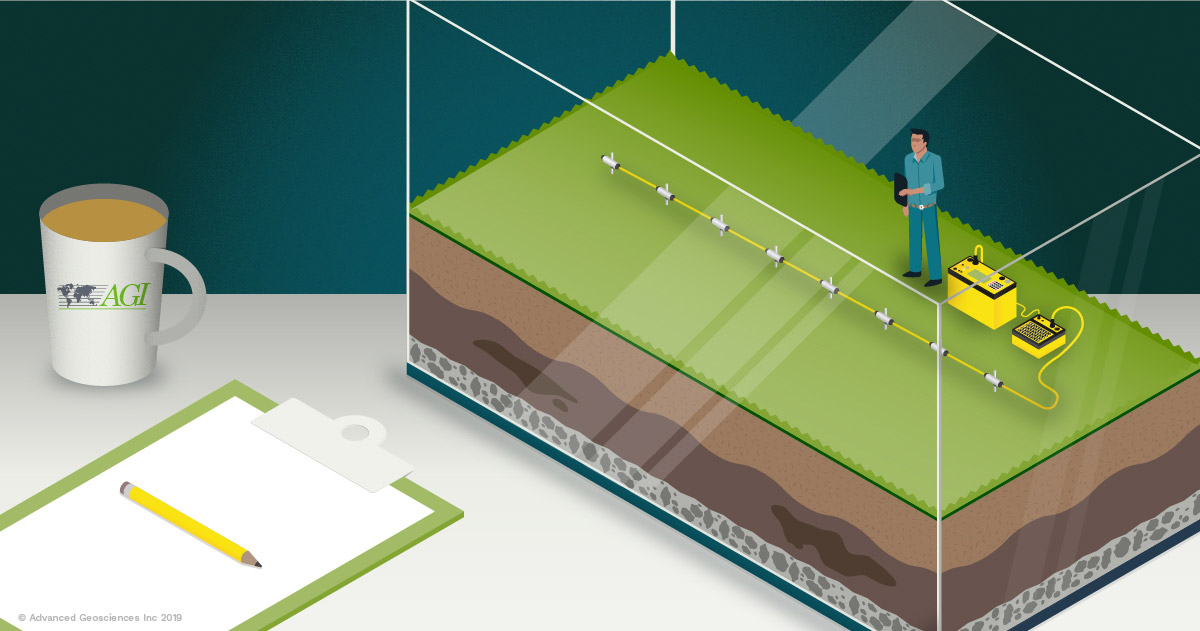
In the academic world, small-scale resistivity tests come up a lot. Often, researchers need to demonstrate the theory in action. And even more often, they don’t have the space to set up a standard cable of electrodes.
With tools like the SwitchBox Grid®, researchers can create and use DIY electrode cables that are more manageable for small-scale in-class demonstrations. (Psst...we've snuck in a video explaining the SwitchBox Grid® at the end of this post)
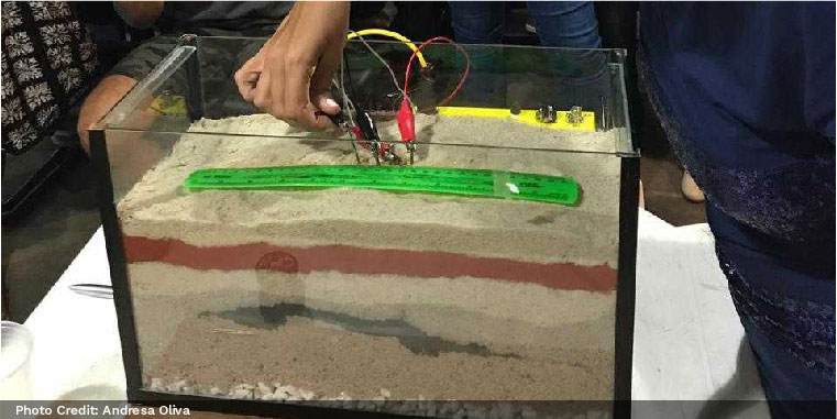
Pictured Above: Professor Andresa Oliva demonstrating a small-scale survey to her students
Here’s how to use the SwitchBox Grid® for small-scale tests. We’ve included instructions for measuring in liquid and solid materials. You can follow the instructions below regardless of if you’re scaling down a 1D, 2D, 3D, 4D, or borehole-to-borehole survey.
Materials Needed:
-
A small tank made of electrically insulating material (preferably a container that you can see through)
-
A ruler with millimeter spacing
-
Stainless steel nails to be used as electrodes
-
Enough water to fill your tank halfway (if doing a scaled marine survey)
-
Enough sand, soil, rocks, etc. to fill your tank at least halfway (if doing a scaled survey of solid materials)
-
Insulating and non-absorbent material like PVC plastic (if doing a scaled marine survey)
-
DIY electrode jumper cables (Insulated wire with an alligator clamp on one end and standard banana plugs on the other end)
-
SwitchBox Grid®
-
Resistivity Imaging Meter (such as the SuperSting™)
-
A command file (.cmd)
Create a Command File:
Regardless of what kind of survey you’re testing, you’ll need to create a command file (.cmd) beforehand.
If you’re using AGI products, you have two options to create a .cmd file. You can use the CommandCreator which is found in the SuperSting™ Administrator software (SSM App) or the AGI EarthImager™ inversion modeling software. EarthImager™ inversion modeling software suite can create Expanding Dipole-Dipole, Gradient, StrongGradient and Bipole-Bipole (used in borehole-to-borehole scenarios) arrays.
Visit AGI Help Desk To Learn How To Make A Command File in the SSM App.

Performing a Small-Scale Test with solid materials (Sand, soil, rocks, etc.):
A sandbox tank setup can be created by adding layers of sand, soil, clay, rocks, and moisture to approximate stratigraphy. You’ll want to fill the tank at least half-full with layered materials.
Install electrodes so that you can create an array for your survey. Small stainless steel nails work well for this—unless you are modeling the effects of the electrode material.
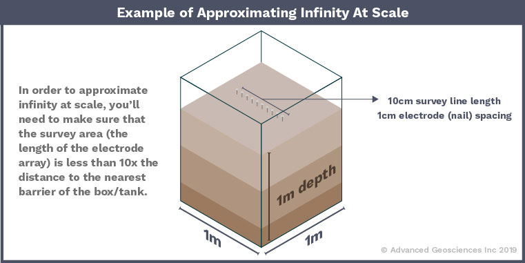
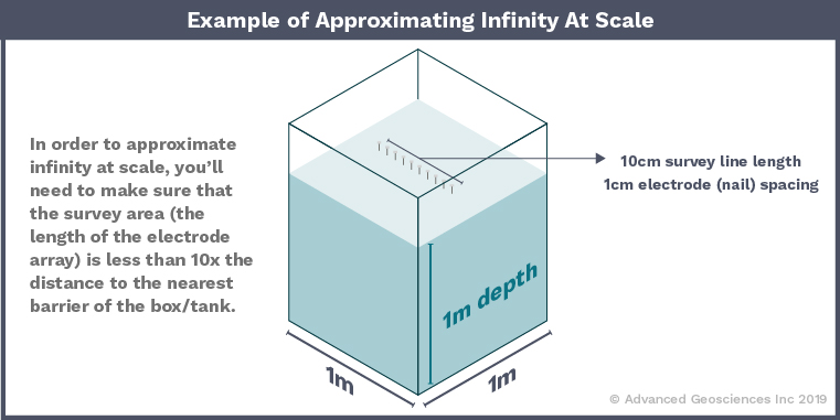
If you’re not modeling the box/tank itself, then you’ll need to approximate infinity. In order to approximate infinity at scale, you’ll need to make sure that the survey area (the length of the electrode array) is less than 10x the distance to the nearest barrier of the box/tank.
So for example:
If the Sandbox/Tank is 1m x 1m x 1m then your electrode array should be no longer than 10cm in length.
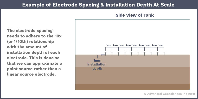
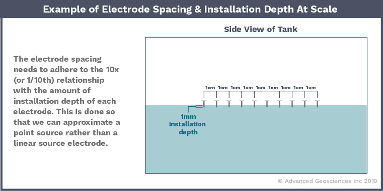
The electrode spacing needs to adhere to the 10x (or 1/10th) relationship with the amount of installation depth of each electrode. This is done so that we can approximate a point source rather than a linear source electrode.
So for example:
If the electrode spacing is 1cm, then the stainless steel electrode (nail) should not penetrate the surface more than 1mm.
This isn’t a hard rule as it isn’t solely the electrode spacing that ultimately dictates this relationship—it is the transmitter/receiver dipole size that we need to consider and the electrode-to-ground contact resistance (CRS). When the dipole size is the size of the unit electrode spacing, then we need to adhere to the 10x (or 1/10th) scale. If the contact resistance is too high, then the resistivity meter’s transmitter will not be able to output enough electrical current into the material. The only recourse then is to drive the electrodes further into the material.
Clip an insulated multi-stranded conductor to each stainless steel nail. On the other end of the conductor should be a standard banana plug, which will plug into the faceplate on the SwitchBox Grid®. Make note of which electrode is connected to which numbered electrode socket on the Grid.
Connect your SwtichBox Grid® to your resistivity meter and run your survey!
Performing a Small-Scale Test with liquid material:
Fill the tank about halfway with water (fresh or saline). A water tank setup allows you to control the background resistivity easily.
Install electrodes so that you can create an array for your survey. Again, small stainless steel nails work well for this—unless you are modeling the effects of the electrode material. Graphite can also be used, but it is subject to wear and tear more than stainless steel nails.
There are a few ways you can install your array.
-
Hang the array at the water surface while only letting the tips of the stainless steel nail electrodes dip into the water of the tank.
-
Another approach is to lay the electrodes on the tank bottom. In a sense, this is like flipping the tank model upside down.
-
Create an electrode frame. Mount the array of nails on a frame made from an insulating material that doesn’t absorb moisture (we recommend small pieces of PVC plastic). An array of stainless steel nails that are evenly spaced in a line or grid works best.
PRO TIP:
To increase the current output you may need to submerge the stainless steel nails further to lower the contact resistance and/or increase the conductivity by adding a small amount of salt to the deionized water. A little salt will go a LONG way, so don’t over do it.
NOTE: The rest of the steps are identical to steps for solid-material surveys.
If you’re not modeling the box/tank itself, then you’ll need to approximate infinity. In order to approximate infinity at scale, you’ll need to make sure that the survey area (the length of the electrode array) is less than 10x the distance to the nearest barrier of the box/tank.
So for example:
If the Sandbox/Tank is 1m x 1m x 1m then your electrode array should be no longer than 10cm in length.
The electrode spacing needs to adhere to the 10x (or 1/10th) relationship with the amount of installation depth of each electrode. This is done so that we can approximate a point source rather than a linear source electrode.
So for example:
If the electrode spacing is 1cm, then the stainless steel electrode (nail) should not penetrate the surface more than 1mm.
This isn’t a hard rule as it isn’t solely the electrode spacing that ultimately dictates this relationship—it is the transmitter/receiver dipole size that we need to consider and the electrode-to-ground contact resistance (CRS). When the dipole size is the size of the unit electrode spacing, then we need to adhere to the 10x (or 1/10th) scale. If the contact resistance is too high, then the resistivity meter’s transmitter will not be able to output enough electrical current into the material. The only recourse then is to drive the electrodes further into the material.
Clip an insulated multi-stranded conductor to each stainless steel nail. On the other end of the conductor should be a standard banana plug, which will plug into the faceplate on the SwitchBox Grid®. Make note of which electrode is connected to which numbered electrode socket on the Grid.
Connect your SwtichBox Grid® to your resistivity meter and run your survey!
Learn More:
Visit AGI Help Desk To Learn How To Make A Command File in the SSM App.
