- Office Hours: M-F 8:30 AM - 5:00 PM
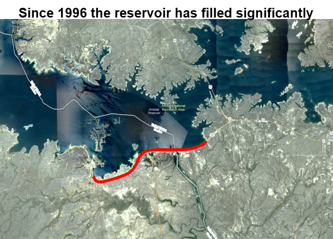
In 1996, the Comision Federal de Electricidad (CFE), the national electric company of Mexico responsible for the Mexican half of the Amistad Dam, contacted AGI. The CFE heard about the capabilities of our instruments and were anxious to see if our tools could help them solve their problem: The dam was emptying itself, and thus, failing at flood control, power generation, and recreational use.
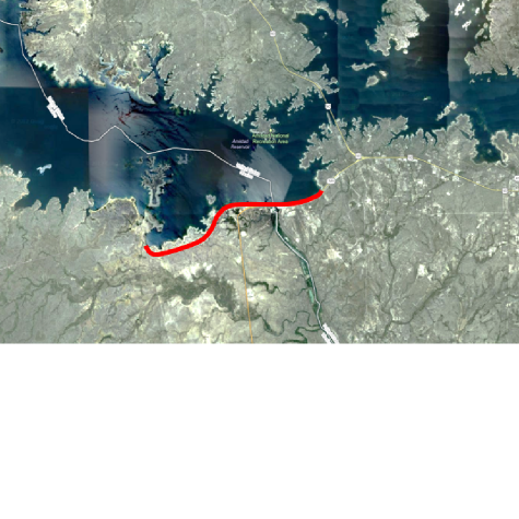
Amistad Dam is the largest of the storage dams and reservoirs built on the international reach of the Rio Grande River and was dedicated in 1969 by United States President Richard M. Nixon and Mexico President Diaz Ordaz.
The dam is 6.1 miles (10 kilometers) long and stands 254 feet (77.4 meters) above the riverbed; it consists of a concrete gravity spillway section within the river canyon flanked by earth embankments (IBWC). It is owned and operated jointly by the United States and Mexico.
Acid rain would find its way through small fractures in the limestone, which causes the limestone to slowly dissolve so that the rock’s fissures and fractures, slowly widen. Eventually, this caused collapses where water rushed through until a sinkhole appeared. Engineers observed holes up to 5m diameter opening in the bottom of the dam that were emptying the dam completely. In places, water was moving in a circular motion, and over time, that circular movement sped up, eventually causing water to disappear into the ground—much like a drain empties water in a bathtub. Engineers uncovered that the water was going downstream, below the dam, and needed to find the path where the water rushed out under the dam.
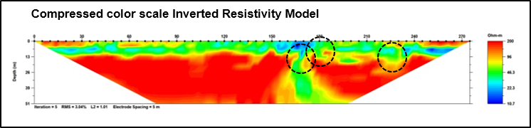
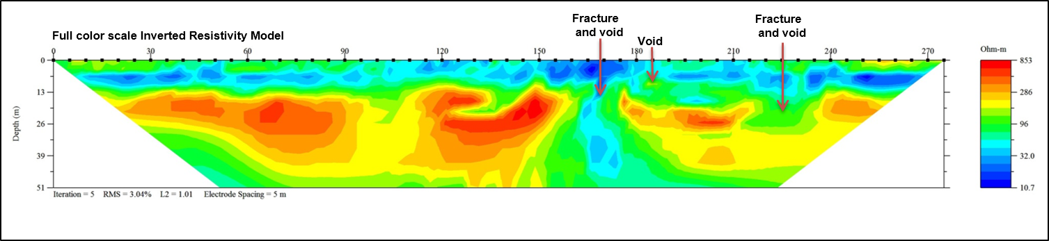
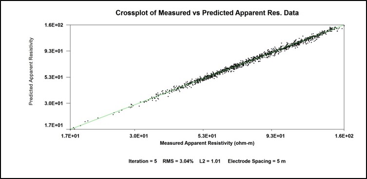
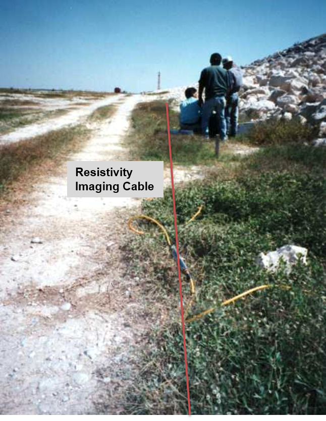
In order to identify where water was breaking through the grout curtain, we used a 56-electrode Sting/Swift system. We tested three different arrays recorded on the same electrode layout: Dipole-Dipole, Schlumberger, and Wenner. The array of 56 steel electrodes was located at the bottom of the dam in a drained part near the wall. They were placed at five-meter intervals along the survey line. A Swift Smart Electrode cable consisting of four 14-switch segments was connected for this test. The Sting R1 instrument was prepared with two user-defined measurement programs: one for the Schlumberger method and the other for the Wenner method. The measurements were automatically recorded by Sting using these two loaded programs and the built-in Dip-Dip program for a total of three different recordings on the same site using the same electrodes.
Dipole-Dipole array: 688 readings in 2 hours, 35 minutes.
Wenner array: 495 readings in 1 hour, 56 minutes.
Schlumberger array: 426 readings in 1 hour, 39 minutes.
These three contrasting data sets showed us the following:
The Dipole-Dipole array was far superior in terms of resolution and depth penetration.
The Wenner had little-to-no ability to resolve the known fracture and was basically useless resolving lateral changes at depth.
The Schlumberger—while it didn't quite have the resolving power of the Dipole-Dipole array—did show some indication of the known fracture. It had a stronger signal to noise ratio than that of the Dipole-Dipole array.
However, the SuperSting™ instrument is noise insensitive, and it rarely needs to rely on the Schlumberger or the Wenner array for a stronger signal level. There are other implications to now wanting to use the Wenner array. The Wenner array (on top of being less resolving) is a single channel array which means that the time to collect the data is slow if you can't utilize all eight channels.
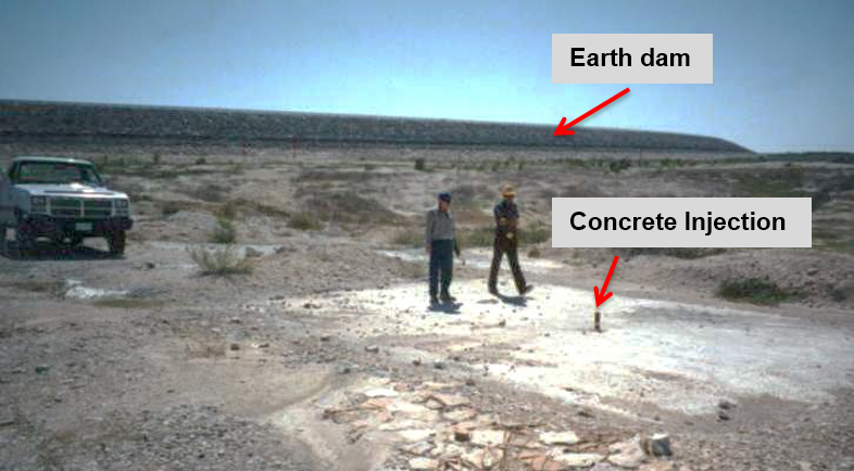
Based on the survey and the data AGI’s instruments were able to provide, the anomalies centered around the local coordinates 565 and 620 were drilled and grouted. The anomaly around 565 was designated a fracture zone with an associated cave and the anomaly at 620 was designated as a cavity. The two systems were injection grouted using 703 cubic meters of a mixture consisting of 50% water, 14% cement and 36% sand.
CFE purchased two instruments, which they began to use routinely to find fractures, which could then be easily grouted as part of the ongoing maintenance process of the dam.
Accurate Location Of Fractures & Drilling: It would be very expensive to drill individual holes to locate fractures—unfortunately, this low-tech route is often taken. Most often when you drill, you drill vertically; to find a fracture like this, you have to drill tons of holes, which is both inefficient and cost-prohibitive. The trick is to locate the fractures and drill right into them, which is what AGI’s instruments allow.
Savings: AGI’s instruments were the best way for CFE to save money by quickly locating leakage in the dam. Dams require routine maintenance, and the AGI solution—to use instruments to find the actual locations of water leakage instead of guessing and drilling—saves time, labor, and material costs.
You can use this method to locate water in any application—from relief aid, to dam leakage, to any circumstance where you’re looking for water underground.
We have retired the instrument used in this example, the Sting R1. We recommend the SuperSting™ for surveys like this because it expedites the survey (you can collect and record data up to 15 times faster than with the Sting R1).