- Office Hours: M-F 8:30 AM - 5:00 PM
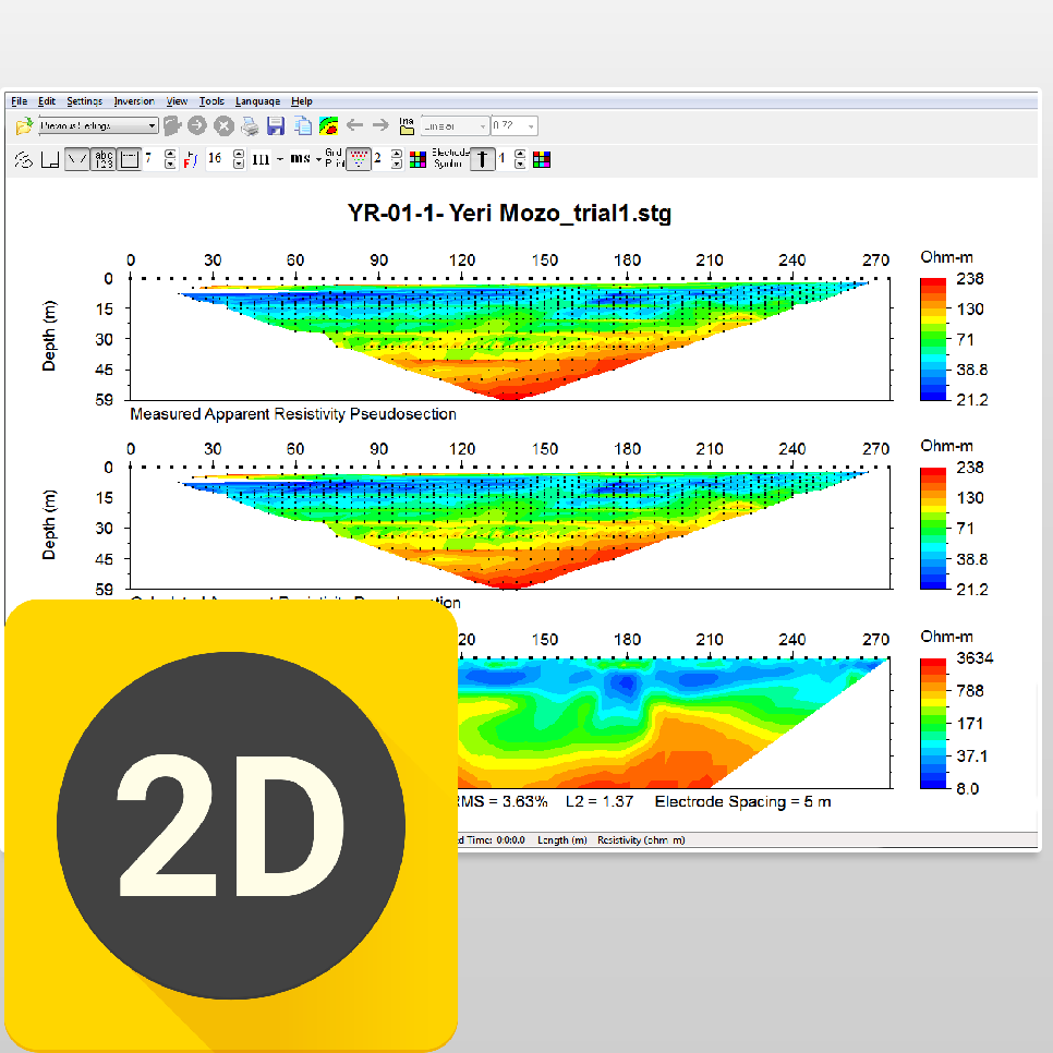
AGI EarthImager™ 2D is a two-dimensional inversion modeling software for affordable resistivity and induced polarization (IP) imaging. It interprets data collected by the SuperSting™ Wi-Fi in just a few clicks, including parallel boreholes or on a surface line.
The data set, collected using SuperSting™ Wi-Fi earth resistivity imaging instruments, is processed into a 2D cross-section of the earth. The processed data can be output to various types of files and can be processed into reports ready for submission to the client.
Any array or mixed data from Schlumberger, Pole-Pole, Pole-Dipole, Dipole-Dipole, or Wenner electrode arrays are possible to invert. A special "Survey Planner" allows the user to enter a geological model and run a virtual survey and then invert the virtual data to see if the objective of the survey can be met.
EarthImager™ 2D is for use in geotechnical and geologic industries, including the following applications:
Cave and void detection
Depth-to-bedrock mapping
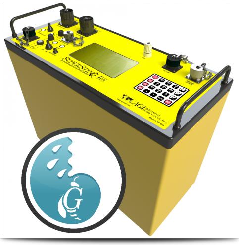
Ground water exploration
Mineral exploration
Mapping environmental spills
Monitoring environmental cleanup progress
Aggregate mapping
Determining the best location for a well in a rural, underdeveloped area—so the individuals in the surrounding area have access to safe and clean drinking water—is an excellent use of the EarthImager™ 2D. Drilling is expensive and drill maintenance is even more so, so if an non-governmental organization (NGO) decides to drill a new well, they need to know with certainty where to place it. By using EarthImager™ 2D, the ground water exploration team can create a tomogram that shows where the best location for a producing well is.
User-friendly Windows GUI.
Seamless operation with AGI resistivity instruments.
Survey planner with graphical model input, virtual survey with the actual command file, and inverse simulation with user-specified Gaussian noises.
Topographic correction and printout of resistivity section with topographical features.
Data editing for detecting and removing erroneous data points and bad electrodes.
No software limit on number of data or number of electrodes.
No limit on electrode array type or electrode location.
Inversion progress bar to show the inversion status.
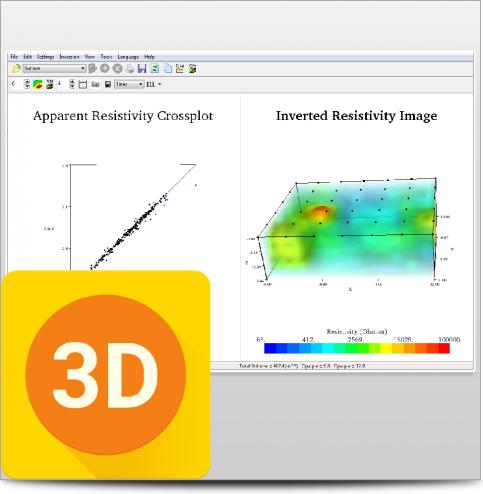
Data misfit scatter plot and cross-plot.
Reversal and horizontal shift of a profile.
High-definition report quality plat-style printout.
Batch inversion of many data files.
Borehole command creator for AGI SuperSting™ instruments.
Support of other instrument brands’ data file format.
Finite difference and finite element forward modeling.
Options of boundary condition for forward modeling.
Three inversion algorithms: damped least squares, smooth model, and robust inversion.
IP data processing by linear inversion.
Uses Gauss-Newton and quasi-Newton methods.
Both root-mean-squared (RMS) error and L2-norm statistics to monitor the inversion progress and convergence.
Windows TrueType font and true 24-bit color.
Fast graphics with automatic refresh and scalable image.
Real-time scrolling through all iterations using the mouse wheel, creating "movie-like" animation.
Noisy data suppression.
A graphical a-priori information input interface.
Removable contour curves and automatic blanking.
Windows TrueType font and true 24-bit color.
Trackable and retrievable user settings.
Tool buttons and pop-up menus for easy access to frequently used menu items.
Well-organized and hassle-free processing directory structure.
Automatic file-saving feature with on/off options.
Retrievable inversion output/log file.
Saveable as bitmap, JPEG, or Windows metafile files at three resolution levels.
Saveable in XYZ format so it can be loaded into any off-shelf graphics software.
Check of computer memory status to estimate processing capability.
Convergence curve display.
This product is qualified for 100% financing. Learn more.


")


When you can see what you're working with below the surface, you can make better decisions that save you time and money.