We like to dig into various topics on our blog. One method that we want to drill into today is the borehole-to-borehole electrical resistivity survey.
We’ve broached the subject of borehole-to-borehole surveys a couple of times on our blog. We mentioned it in our post about the Bipole-Bipole array and our Panama seminar recap. The Panama case is fascinating because it utilizes our SwitchBox Grid and DIY cables. Today, let’s delve into the concept of this survey, walk through the step-by-step process, and unearth its applications in groundwater and mineral exploration, as well as other subsurface investigations. (We’re all out of borehole puns, we promise.)

Understanding Borehole-to-Borehole Electrical Resistivity Surveys
As the name suggests, a borehole-to-borehole electrical resistivity survey is a technique employed to measure the electrical resistivity of the subsurface between two boreholes. By injecting an electrical current into one borehole and measuring the voltage between two electrodes located in the same or another borehole, we can determine the resistivity of the surrounding subsurface materials. The resolution is uniform, no matter what depth you are scanning.
Applications of Borehole-to-Borehole Electrical Resistivity Surveys
The information obtained from borehole-to-borehole electrical resistivity surveys is invaluable in various fields. Here are some key applications:
-
Groundwater Exploration:
- We can identify potential sites with high water-bearing capacity by analyzing the resistivity distribution between boreholes. This knowledge aids in optimizing the placement of wells and extracting groundwater resources efficiently.
- Preferential flow paths of groundwater and pollutants can be discovered by scanning the region between the boreholes two consecutive times. The first scan will be of the unaltered formation resistivity. The second scan is performed after introducing a weak tracer. The most common tracer is NaCl (table salt). Very little NaCl will alter the resistivity of the fluid enough to see a contrast. This doesn’t mean adding so much that it ruins the potability of the water. A little salt will go a long way and be undistinguishable by taste. I.e., Drinking water regarded as good water quality has 600mg/L TDS. The flow path is discovered after performing a Difference Inversion where two scans are compared to each other. For example, our EarthImager software focuses on the differences between the two scans revealing what changed from one scan to another. Of course, the salt will mainly affect the fluid rather than the formation. This subtracts out the common values created by the formation and highlights the areas where water is.
- We can identify potential sites with high water-bearing capacity by analyzing the resistivity distribution between boreholes. This knowledge aids in optimizing the placement of wells and extracting groundwater resources efficiently.
- Mineral Exploration: Different minerals exhibit distinct electrical resistivity properties. Borehole-to-borehole resistivity surveys enable us to detect and locate mineral deposits by studying the resistivity variations in the subsurface.
- Subsurface Geology Investigations: Borehole-to-borehole resistivity surveys provide detailed information about the subsurface geology and anomalies. This is crucial for identifying potential risks such as subsurface voids, changes in soil composition, or stability issues that can impact infrastructure development or land use planning.
- Environmental Assessments: Environmental concerns are at the forefront of governmental priorities—borehole-to-borehole resistivity surveys aid in assessing subsurface geology and identifying anomalies that may impact the environment. Governments can proactively safeguard the environment and ensure sustainable practices by locating underground storage tanks, contaminated soil, or unstable slopes.
- Construction & Infrastructure Planning: Robust infrastructure is the backbone of societal development. Governments employ resistivity surveys to gain insights into subsurface conditions that impact infrastructure projects. By identifying soil variations, subsurface voids, or unstable ground, governments can design and construct roads, bridges, and water supply systems that withstand the test of time. Tomography below structures like buildings can be difficult for surface arrays since electrodes are rarely drilled through the foundation. Horizontal boreholes to image beneath foundations and other structures which would otherwise not be accessible. This allows imaging of potential voids and other soil conditions impacting the structures.
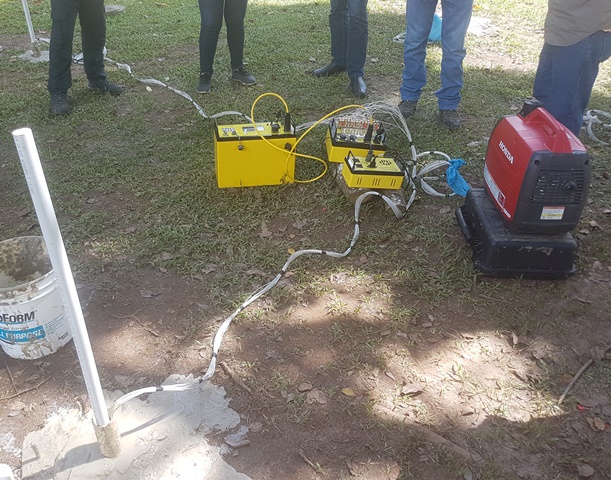
The Process
This type of survey requires a few extra steps than a straightforward Dipole-Dipole survey, but as with any array, it has its purposes. Performing a borehole-to-borehole electrical resistivity survey requires careful planning and execution.
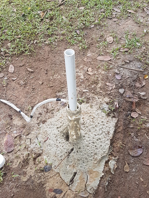
Begin by drilling two boreholes at the desired locations, ensuring they are spaced apart appropriately based on your survey objectives. The boreholes should not exceed a 2:3 ratio in separation vs. depth (I.e., if your borehole is 30 feet deep, the separation should not exceed 20 feet).
We can simulate the electrical current flow and voltage measurements between boreholes through mathematical models such as the finite-difference or finite-element method created by the AGI EarthImager 2D and 3D software suite. This process allows us to understand how different subsurface structures and materials affect the resistivity measurements.

Considerations:
While borehole-to-borehole electrical resistivity surveys are a valuable technique for subsurface investigations, they do come with potential complications:
- Limited Coverage: Borehole-to-borehole surveys provide information only along the direct line between the boreholes. This restricts the spatial coverage and can result in limited lateral resolution of the subsurface resistivity model. To overcome this limitation, additional boreholes or complementary geophysical methods may be necessary to enhance the overall understanding of the subsurface.
- Borehole Conditions: The boreholes' quality and condition can impact the survey results' accuracy. Irregular borehole walls, borehole fluid contamination, or borehole caving can introduce uncertainties and distort the measured voltage and current values. Careful attention must be given to borehole preparation and maintenance to minimize these complications.
- Electrode Positioning: Accurate electrode placement is critical for reliable resistivity measurements. Errors in electrode positioning can lead to distortions in voltage measurements and subsequent inaccuracies in the resistivity model. Careful calibration and precise positioning techniques are required to minimize these errors.
- Interpretation Challenges: Interpreting resistivity data from borehole-to-borehole surveys requires expertise and careful consideration of geological and hydrogeological factors. Correlating resistivity values with specific subsurface features, such as lithology, porosity, or fluid content, requires cautious interpretation. Other geological factors that may affect resistivity, such as fractures, fault zones, or complex geological structures, must be explicitly captured in the resistivity model.
- Cost and Logistics: Borehole-to-borehole surveys can be resource-intensive. Drilling multiple boreholes, deploying logging tools, and conducting survey operations require additional investments beyond a typical survey that uses a surface array. Accessing suitable locations for boreholes and coordinating drilling operations can present logistical challenges, especially in urban or remote areas.
Keeping these considerations in mind allows practitioners and researchers to plan their surveys effectively, mitigate uncertainties, and consider complementary methods or techniques to address limitations.
Borehole-to-borehole electrical resistivity surveys remain a valuable tool for subsurface investigations when implemented with careful consideration and expert interpretation.
