
In this blog post, we’re discussing ponds with leaking geomembrane liners. And more specifically, flexible and impermeable plastic liners. If the techniques in this article interests you, you may want to check out a similar article about detecting leaks in earthen dams and levees.
Ponds can serve as an attractive asset that adds value to your property. In industrial applications ponds can hold strong solvents. Whether it’s for practical or aesthetic purposes, the whole point of a pond is to store a body of fluid. So if your pond is leaking—it can be a costly problem. In industrial cases fines may be incurred. Looking for where a leak is in your liner can also be a time-consuming task. Luckily, resistivity measurements can help save you time in detecting where the leakage is occurring in your pond—without having to remove any water.
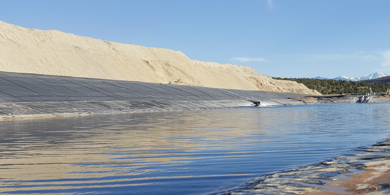
Above - Example of a pond with a plastic geomembrane liner
Speaking of saving time—first, you should rule out evaporation before looking for a leak in your liner.
It’s important to keep in mind that your pond fluid levels will decrease naturally due to evaporation—especially if you’re in a climate of extremely hot weather. Most experts suggest that in the very worst conditions, you should lose less than 8 inches (20.3 cm) of water in a 2-week time span due to evaporation. During a typical summer, you’ll most likely lose about half an inch of water a day. Any more than this could mean a leak in your liner.
So if you’ve already ruled out evaporation as the problem, let’s continue.
If a leak is suspected, you don’t want to waste the time and money looking for it. Alternatively, if you’re a contractor that is offering liner repair services, you’ll want to be confident that you can get the job done quicker than your competitors. This is where electrical resistivity comes in. With this geophysical method, you can find the figurative "needle in the haystack".
How are the leaks detected with electrical resistivity?
Using an array of transmitter and receiver electrodes, you can locate leaks by proxy when you look at where electrical current leaks through the liner. Once spikes in voltage are located, you can further confirm the proxy liquid leak by examining the polarity of the measured voltage at a Dipole over the suspected leak. As you’ll see below, you can use a floating array of dipoles on the surface of the water—so there’s no need to drain your pond. A polarity change in measured voltage occurs as the receiving dipole is moved above a leak in the liner. The inflection point where the voltage changes polarity will be the location of the liner hole.
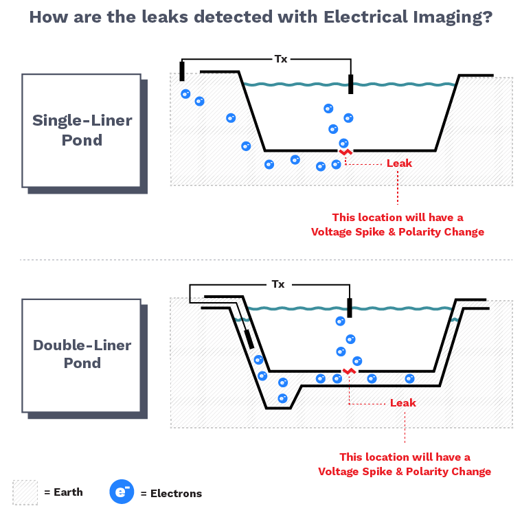
Regardless of if your pond uses a single liner or a double liner, the method is basically the same. The only difference is where you'll be placing your transmitters. As you can see above, if you have a single-liner pond, you'll have a remote transmitter and a transmitter inside of the pond. If you have a double-liner pond, then you'll be placing a transmitter in between the liners and a transmitter that goes inside the pond.
What does a leak look like in the data?
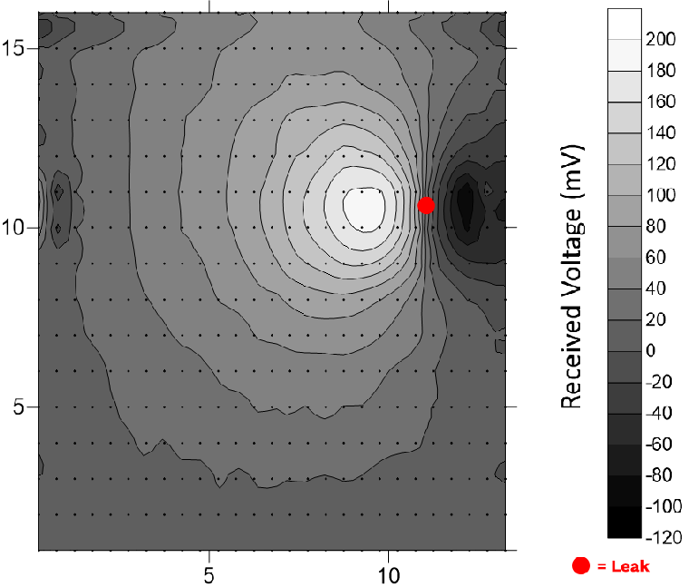
Like we mentioned above, you’re going to be looking for spikes in voltage as well as a polarity change. Below is an example contour plot of a strong response to a leak of only ~1cm in a pond with a plastic liner. We used Golden Software's Surfer in order to make this contour plot of Received Voltages.
The small black dots are where the electrodes were placed (using the Automatic method that we explain below). You can see on the plot where there was an obvious inflection point where a spike in positive and negative voltages met. At the center of this inflection—where the red dot is located—is where the leak was.
How to apply this method
To apply this geophysical method to detect leakage is quite simple. First, you’ll want to conduct a survey that spans the entire surface area of the pond, much like the black dots (electrodes) in the contour plot above span the entirety of the pond. There are two ways you can go about this: that manual way and the automatic way.
Using the manual survey method, you will drag a dipole (on a non-conductive flotation device) from one end of the pond to another while scanning in regular increments. We call this the manual method because you will need to manually control your dipole positioning—perhaps by being in a boat next to the flotation device. However, we prefer the automatic method which is much quicker.
With the automatic method, you would use a waterproof multi-electrode cable that spans from one end of the pond to the other. Then, use your metering instrument to automatically scan dipoles along the cable (illustrated below). From our experience using a SuperSting™, a 50-meter line should scan in about three minutes.
Regardless of your survey preference, continue scanning in parallel lines until you’ve scanned the entire pond. If you use the manual method, keep good notes on your dipole positioning as you’ll need that later.
Next, look at the data to find polarity changes in the measured voltages. As you saw in the contour plot above, the dipole position where there is a polarity change is where your leak is. You can also look at each individual line in something as simple as an XY point plot.
Why does this work?
Well, we know that plastic is an insulator so it won't pass any current through unless there is a puncture of some kind. Even an extremely small puncture will allow current to pass through (technically at the electron size!). If we drive current with a transmitting dipole with one electrode outside of the pond's liner and the other inside the pond's liquid, then any voltage spike at the floating receiving dipoles is related to a leak by proxy. There have been leaks located as small as ~1cm using this method. We find that most leaks in pond liners are found at weaknesses along heat or chemical welded seems, so they tend to be elongated and linear and larger than 1cm.
What can impact your survey?
Any conductive structures could mask leaks in your data. If there are any conductive paths in your pond such as pipes, pumps, etc., you will want to isolate those structures before surveying or make note of them. You can leave them, but the leak detection immediately around these structures will be compromised. Also, clear off any earthen material that may be on top of the edges of the geomembrane that touches the water's edge. This can cause a ground loop into the pond from the transmitter dipole that will mask the proxy leaks you are looking for. If the earth cannot be removed, we have seen that some operators simply lower the pond level slightly with pumping to expose a bare plastic liner below the earth's edge. If you have questions about an upcoming project, as always, reach out to AGI for assistance and guidance.
Learn More
If you want to learn more about the American standards for leak detection, you can purchase the ASTM D7007-03 Standards for Leak Detection here.
