- Office Hours: M-F 8:30 AM - 5:00 PM
The SuperSting™ Wi-Fi is a next-generation electrical resistivity meter and induced polarization (IP), and self-potential (SP) system, used to scan and image the subsurface of the earth and visualize the results in 2D slices or 3D volumes. The fully automated SuperSting™ has been thoroughly field-tested on every extreme environment on earth, utilized in over 700 peer-reviewed journal articles, and provides the highest accuracy and lowest noise levels in the industry. The SuperSting™ line of electrical resistivity tomography equipment is the first in the industry to have multi-channel capability and is continually improved and updated with additional features. With the included tablet, you can control the SuperSting™ Wifi from up to 100m away!
There are five models of the SuperSting™ available (which can be upgraded simply from anywhere in the world by use of a license code):
R1 (single channel)
R2 (two channel)
R4 (four channel)
R6 (six channel)
R8 (eight channel)
Traditional vertical electrical sounding (VES)
Mise-a-la-masse measurements
Multi-electrode electrical tomography (imaging) in 2D, 3D, and 4D
Groundwater Exploration
Imaging Dams & Levees
Marine Dredging
Borehole Tomography
Monitoring Landfills
Mine Leach Piles
Gold Exploration
Mineral Exploration
Borehole-To-Borehole Tomography
Marine Measurements
Imaging Tree Trunks
Imaging Vertical Walls
Imaging Inside Tunnels
Imaging Over Pyramids
Locating Graves
CO2 Sequestration Time-Lapse Monitoring
Dipole-Dipole (8-Channel)
Bipole-Bipole (8-Channel)
Pole-Bipole (8-Channel)
Pole-Pole (8-Channel)
Gradient (8-Channel)
StrongGradient™ (8-Channel)
EdgeGradient™ (8-Channel)
Radial Dipole-Dipole
Inverse Schlumberger (4-Channel)
Mixed Arrays
Dipole-Dipole-Gradient
Wenner-Schlumberger
Schlumberger (Single-Channel Only)
Schlumberger inverse
Wenner (Single-Channel Only)
User Programmable Arrays Of Any Kind
This product is qualified for 100% financing. Learn more.


|
Item |
Description |
|
Measurement Modes |
Apparent resistivity, resistance, induced polarization (IP), SP, and battery voltage. |
|
Measurement Range |
+/- 10Vp-p. |
|
Measuring Resolution |
Max 30 nV—depends on voltage level. |
|
Screen Resolution |
4 digits in engineering notation. |
|
Transmitter |
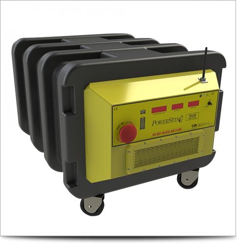
200W internal transmitter. 5kW, 10kW and 15kW external transmitters also available (see separate brochure). |
|
Output Current |
1 - 2000 mA continuous, measured to high accuracy. |
|
Output Voltage |
800 Vp-p—actual electrode voltage depends on transmitted current and ground resistivity. |
|
Input Channels |
Five models available—8-, 6-, 4-, 2-, or 1-channel. |
|
Input Gain Ranging |
Automatic—always uses full dynamic range of receiver. |
|
Input Impedance |
>150 MOhm. |
|
SP Compensation |
Automatic cancellation of SP voltages during resistivity measurement. Constant and linearly varying SP cancels completely (V/I and IP measurements). |
|
Type Of IP Measurement |
Time domain chargeability (M). Six time slots measured and stored in memory. |
|
IP Current Transmission |
ON+, OFF, ON-, OFF. |
|
IP Cycle Times |
0.5, 1, 2, 4, and 8 s. |
|
Measure Cycles |
Running average of measurement displayed after each cycle. Automatic cycle stops when reading errors fall below user set limit or user set max cycles are done. |
|
Resistivity Cycle Times |
Basic measure time is 0.2, 0.4, 0.8, 1.2, 3.6, 7.2, or 14.4 s as selected by user via keyboard. Autoranging and commutation adds about 1.4 s. |
|
Signal Processing |
Continuous averaging after each complete cycle. Noise errors calculated and displayed as percentage of reading. Reading displayed as resistance (dV/I) and apparent resistivity (ohmm or ohmft). Resistivity is calculated using user-entered electrode distances. |
|
Noise Suppression |
|
|
Total Accuracy |
Better than 1% of reading in most cases (lab measurements). Field measurement accuracy depends on ground noise and resistivity. Instrument will calculate and display running estimate of measuring accuracy. |
|
System Calibration |
Calibration is done digitally by the microprocessor based on correction values stored in memory. |
|
Supported Configurations |
|
|
Operating System |
Stored in reprogrammable flash memory. Updated versions can be downloaded from our website and stored in the flash memory. |
|
Data Storage |
Full resolution reading average and error are stored along with user-entered coordinates and time of day for each measurement. Storage is effected automatically in a job-oriented file system. |
|
Data Display |
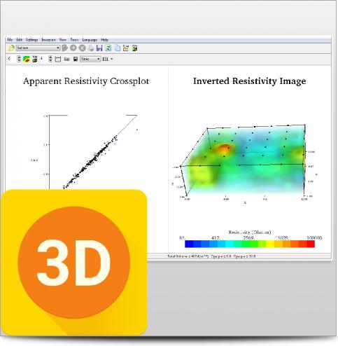
Apparent resistivity (ohmmeter), current intensity (mA), and measured voltage (mV) are displayed and stored in memory for each measurement. Data can also be displayed on an Android device in real time as bright color pseudosections, IP curves, transmitter/receiver plot, contact resistance measurements, and more. |
|
Memory Capacity |
Virtually unlimited data storage in real time on controlling Android device. The internal SuperSting memory can store more than 79,000 measurements (resistivity mode) and more than 26,000 measurements in combined resistivity/IP mode. |
|
Data Transmission |
Data can be instantaneously transferred from the Android device by email or by file transfer from the Android device USB port. RS-232C channel available to dump data from instrument to a Windows-type computer on user command. |
|
Automatic Multi-Electrodes |
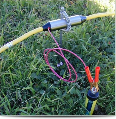
The SuperSting is designed to run dipole-dipole, pole-dipole, pole-pole, gradient, Wenner, and Schlumberger surveys including roll-along surveys completely automatic with the patented Dual Mode Automatic Multi-Electrode system (U.S. Patent 6,404,203) or a passive electrode cable system. The SuperSting can run any other array by using user-programmed command files. These are ASCII files that can be created using a regular text editor. The command files are uploaded to the SuperSting RAM memory and can at any time be recalled and run as a survey. |
|
User Controls |
|
|
Display |
Graphics LCD display (16 lines x 30 characters) with night-light. Android mobile phone screen (7”) or 10” Android tablet with bright color AMOLED display. |
|
Power Supply, Field |
|
|
Power Supply, Office |
DC power supply. |
|
Operating Time |
Depends on survey conditions and size of battery used. Internal circuitry in auto-mode adjusts current to save energy. |
|
Operating Temperature |
-20 to +50°C when controlled by your Android device (phone or tablet). The instrument LCD screen fades out at -5ºC, but the instrument continues to function normally by your Android phone, kept warm in your pocket |
|
Weight |
10.9 kg (24 lbs.). |
|
Dimensions |
|
When you can see what you're working with below the surface, you can make better decisions that save you time and money.